Project
ASME HPVC
Human-Powered Vehicle Design
Aerodynamic evaluation and vehicle-level design integration for a front-wheel-drive human-powered competition trike.
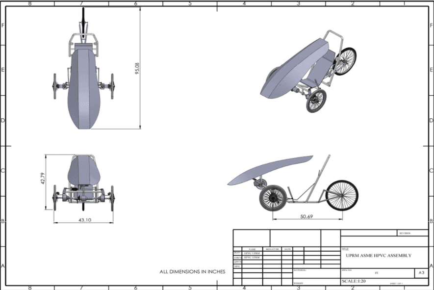
Guacamaya human-powered vehicle design
Project
ASME HPVC
Vehicle
Guacamaya
Primary Role
Aerodynamics Lead
Main Tool
ANSYS Workbench
The Objective
My primary responsibility was to determine whether an aerodynamic fairing would provide enough total vehicle benefit to justify its development.
The evaluation considered more than drag reduction. The fairing would also introduce additional weight, tooling, material cost, manufacturing lead time, visibility constraints, and integration requirements.
My Contribution
Engineering Method
The analysis followed a staged process that connected geometry, CFD validation, aerodynamic performance, and practical manufacturability.
STEP 01
Evaluate whether an aerodynamic fairing could reduce drag enough to justify its additional weight, manufacturing effort, cost, and vehicle-integration requirements.
STEP 02
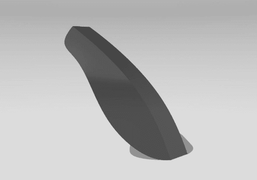
Create a streamlined fairing concept inspired by a teardrop profile while reducing frontal area and maintaining coverage of the rider and vehicle.
STEP 03
Analyze a sphere with a known drag-coefficient range before applying the same CFD workflow to the fairing geometry.
STEP 04
Compare the predicted aerodynamic performance against manufacturing complexity, material requirements, development time, and integration risk.
CFD Evaluation
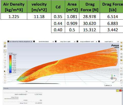
The ANSYS workflow used a k-ε turbulence model, a no-slip boundary condition, and a 25 mph inlet velocity. A sphere with a known drag range was analyzed first to validate the methodology.
Simulation Velocity
11.18 m/s
Equivalent to 25 mph
Target Drag Coefficient
< 0.44
Team design specification
Predicted Fairing Cd
0.35
Reported CFD result
Validation Error
6.41%
Sphere validation case
Design Decision
Do Not Proceed
The proposed fairing was not advanced into manufacturing for the final competition vehicle.
Engineering Tradeoff
The CFD result indicated that the fairing could meet the aerodynamic target. However, an engineering decision must consider the entire system rather than one performance metric.
The expected benefit was weighed against added mass, manufacturing uncertainty, material and tooling requirements, schedule limitations, subsystem clearance, and limited team resources. The team therefore redirected effort toward systems with greater immediate impact on vehicle reliability and competition readiness.
Cross-Functional Design
After the aerodynamic evaluation, I supported the integration of steering, braking, and power-transmission systems located around the front axle.
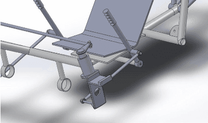
The front axle needed to accommodate steering, braking, drivetrain, and wheel components within the same constrained region.
Front-wheel-drive integration led the team to reconsider the original steering layout and adopt a more compact under-seat mechanism.
The aerodynamic body needed to avoid interference with steering movement, rider visibility, wheel travel, and subsystem maintenance.
Team Design Validation
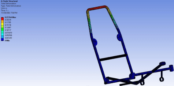
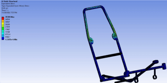
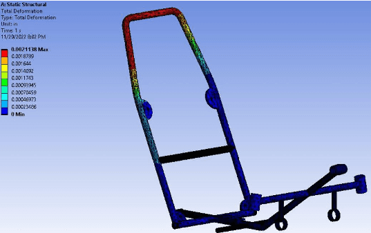
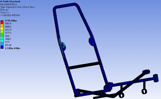
The structural analyses below were completed as part of the overall HPVC team effort. My primary role was aerodynamics, but these results provide important context for the complete vehicle design and its competition requirements.
RPS Top Load
0.58 cm
Maximum deformation
Safety factor: 1.7
RPS Side Load
0.0054 cm
Maximum deformation
Safety factor: 11.6
Weight Distribution
0.083 cm
Maximum deformation
Safety factor: 2.3
Design Gallery
Reflection
A component can produce a measurable performance improvement and still not justify its added weight, cost, manufacturing effort, or development risk.
Comparing the CFD method against a body with a known drag-coefficient range increased confidence before evaluating the custom geometry.
The fairing, steering, drivetrain, brakes, wheels, and frame competed for the same space and required continuous cross-team coordination.
The purpose of analysis is to guide decisions. Eliminating a feature that does not provide sufficient total-system value is a successful engineering outcome.
Technical Documentation
View the complete team report for detailed design selection, structural analysis, aerodynamic methodology, subsystem calculations, testing plans, and competition requirements.